Sign In
Upload
Manuals
Brands
Motorola Manuals
Portable Radio
Professional Radio
Motorola Professional Radio Manuals
Manuals and User Guides for Motorola Professional Radio. We have
1
Motorola Professional Radio manual available for free PDF download: Service Manual
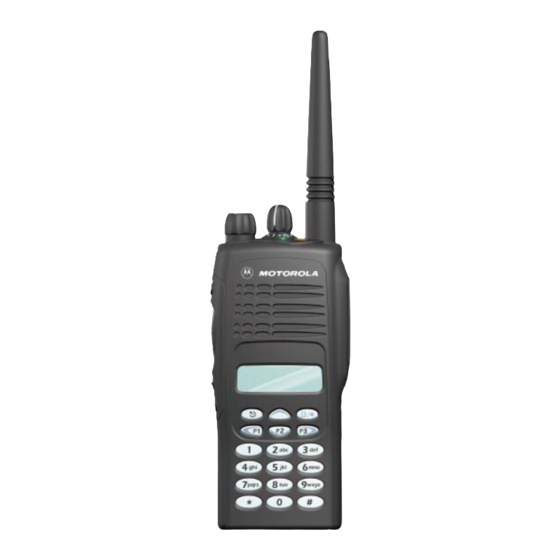
Motorola Professional Radio Service Manual (109 pages)
Brand:
Motorola
| Category:
Portable Radio
| Size: 2.38 MB
Table of Contents
Safety and General Information
3
Operational Cautions
5
Operational Warnings
5
Safety and General
5
Fmrc Approved Equipment
6
Intrinsically Safe Radio Information
6
Do Not Substitute Options or Accessories
7
Repair of Fmrc Approved Products
7
Table of Contents
9
Chapter 1 Introduction
17
Scope of Manual
17
Warranty and Service Support
17
Warranty Period
17
Return Instructions
17
After Warranty Period
17
Related Documents
18
Technical Support
18
Piece Parts Availability
18
Radio Model Chart and Specifications
19
Radio Model Information
19
Chapter 2 Theory of Operation
21
Introduction
21
Radio Power Distribution
21
Figure 2-1:DC Power Distribution Block Diagram
21
Keypad
22
Figure 2-2:Keypad Block Diagram
22
Controller Board
23
Figure 2-3:Controller Block Diagram
23
MCU Digital
23
Real Time Clock
24
Circuit Description
24
Figure 2-4:RTC Circuit
24
MODB/VSTBY Supply
24
Audio/Signaling
25
UHF Transmitter
25
Figure 2-5:UHF Transmitter Block Diagram
25
Power Amplifier (PA)
25
Power Amplifier
25
Antenna Switch
26
Harmonic Filter
26
Antenna Matching Network
26
Power Control Integrated Circuit (PCIC)
26
Temperature Cut Back Circuit
26
UHF Receiver
26
Receiver Front-End
27
Figure 2-6:UHF Receiver Block Diagram
27
UHF Receiver
27
Receiver Back-End
28
Automatic Gain Control (AGC)
28
Frequency Generation Circuit
29
Figure 2-7:UHF Frequency Generation Unit Block Diagram
29
Synthesizer
29
Voltage Control Oscillator (VCO)
30
Figure 2-8:UHF Synthesizer Block Diagram
30
Figure 2-9:UHF VCO Block Diagram
31
VHF Transmitter
32
Figure 2-10:VHF Transmitter Block Diagram
32
Power Amplifier
32
Receiver Front-End
34
Automatic Gain Control (AGC)
35
Receiver Back-End
35
Frequency Generation Circuit
36
Voltage Control Oscillator (VCO)
37
Figure 2-14:VHF VCO Block Diagram
38
Low Band Transmitter
39
Power Amplifier (PA)
39
Figure 2-15:Low Band Transmitter Block Diagram
39
Antenna Switch
39
Harmonic Filter
40
Antenna Matching Transformer
40
Power Control Integrated Circuit (PCIC)
40
Temperature Cut Back Circuit
40
Electrostatic Discharge (ESD) Protection Circuit
40
Low Band Receiver
40
Figure 2-16:Low Band Receiver Block Diagram
41
Receiver Front-End
41
Receiver Back-End
42
Automatic Gain Control (AGC)
42
Frequency Generation Circuit
42
Figure 2-17:Low Band Frequency Generation Unit Block Diagram
43
Synthesizer
43
Figure 2-18:Low Band Synthesizer Block Diagram
44
Voltage Control Oscillators (VCO)
44
Receive VCO
44
Transmit VCO
44
Buffer
44
Diplexer/Output Filters
44
Prescalar Feedback
45
800 Mhz Transmitter
45
Power Amplifier
45
Figure 2-19:800 Mhz Transmitter Block Diagram
45
Antenna Switch
46
Harmonic Filter
46
Power Control Integrated Circuit (PCIC)
46
800 Mhz Receiver
47
Receiver Front-End
47
Figure 2-20:800Mhz Receiver Block Diagram
47
Receiver Back-End
48
Automatic Gain Control Circuit
48
Figure 2-21:800 Mhz Frequency Generation Unit Block Diagram
49
Frequency Generation Circuit
49
Synthesizer
50
Figure 2-22:800 Mhz Synthesizer Block Diagram
50
Voltage Control Oscillator (VCO)
51
Figure 2-23:800 Mhz VCO Block Diagram
51
Trunked Radio Systems
52
Privacy Plus Trunked Systems
52
LTR™ Trunked Systems
52
MPT Trunked Systems
52
Passport™ Trunked Systems
53
900 Mhz Transmitter
54
Figure 2-24:Transmitter Block Diagram
54
Power Amplifier
55
Antenna Switch
55
Harmonic Filter
55
Power Control Integrated Circuit (PCIC)
55
900 Mhz Receiver
56
Figure 2-25:900 Mhz Receiver Block Diagram
56
Receiver Front-End
56
Receiver Back-End
57
Hear Clear IC
57
Automatic Gain Control Circuit
58
Frequency Generation Circuitry
59
Figure 2-26:Frequency Generation Unit Block Diagram
59
900 Mhz Synthesizer
60
Figure 2-27:Synthesizer Block Diagram
60
900 Mhz Voltage Control Oscillator (VCO)
61
Figure 2-28:VCO Block Diagram
61
Chapter 3 Maintenance
63
Introduction
63
Inspection
63
Cleaning
63
Safe Handling of CMOS and LDMOS
64
General Repair Procedures and Techniques
64
Recommended Test Tools
66
Replacing the Circuit Board Fuse
67
Figure 3-1:Uhf/Vhf/Low Band/800Mhz/900Mhz Circuit Board Fuse Locations
68
Removing and Reinstalling the Circuit Board
69
Figure 3-2:Circuit Board Removal and Reinstallation
69
Power up Self-Test Error Codes
69
UHF Troubleshooting Charts
71
Troubleshooting Flow Chart for Controller
71
Troubleshooting Flow Chart for Receiver (Sheet 1 of 2)
72
Troubleshooting Flow Chart for Receiver (Sheet 2 of 2)
73
Troubleshooting Flow Chart for Transmitter
74
Troubleshooting Flow Chart for Synthesizer
75
Troubleshooting Flow Chart for VCO
76
VHF Troubleshooting Charts
77
Troubleshooting Flow Chart for Controller
77
Troubleshooting Flow Chart for Receiver (Sheet 1 of 2)
78
Troubleshooting Flow Chart for Receiver (Sheet 2 of 2)
79
Troubleshooting Flow Chart for Transmitter
80
Troubleshooting Flow Chart for Synthesizer
81
Troubleshooting Flow Chart for VCO
82
Low Band Troubleshooting Charts
83
Troubleshooting Flow Chart for Controller
83
Troubleshooting Flow Chart for Receiver (Sheet 1 of 2)
84
Troubleshooting Flow Chart for Receiver (Sheet 2 of 2)
85
Troubleshooting Flow Chart for Transmitter
86
Troubleshooting Flow Chart for Synthesizer
87
Troubleshooting Flow Chart for VCO
88
800 Mhz Troubleshooting Charts
89
Troubleshooting Flow Chart for Controller
89
Troubleshooting Flow Chart for Receiver (Sheet 1 of 2)
90
Troubleshooting Flow Chart for Receiver (Sheet 2 of 2)
91
Troubleshooting Flow Chart for Transmitter
92
Troubleshooting Flow Chart for Synthesizer
93
Troubleshooting Flow Chart for VCO
94
Passport Trunking Troubleshooting Chart
95
Keypad Troubleshooting Chart
96
900 Mhz Troubleshooting Charts
97
Troubleshooting Flow Chart for Controller (Sheet 1 of 2)
97
Troubleshooting Flow Chart for Controller (Sheet 2 of 2)
98
Troubleshooting Flow Chart for Receiver (Sheet 1 of 2)
99
Troubleshooting Flow Chart for Receiver (Sheet 2 of 2)
100
Troubleshooting Flow Chart for Transmitter
101
Troubleshooting Flow Chart for Synthesizer
102
Troubleshooting Flow Chart for VCO
102
Chapter 4 Schematic Diagrams, Overlays, and Parts Lists
103
Introduction
103
Notes for All Schematics and Circuit Boards
103
Flex Layout
104
Keypad-Controller Interconnect Flex Schematic
105
Keypad-Controller Interconnect Flex Parts List
105
Universal Flex Connector
106
Figure 4-3:Universal Flex Connector
106
Universal Connector Flex Schematic
107
Universal Flex Connector Parts List
107
Keypad Top and Bottom Overlays
108
Advertisement
Advertisement
Related Products
Motorola PRO3150
Motorola PRO2150
Motorola PRO5150
Motorola PRO5450
Motorola PRO7150
Motorola PRO7350
Motorola PRO7450
Motorola PRO9150
Motorola PRO9450
Motorola PRO5350
Motorola Categories
Cell Phone
Two-Way Radio
Baby Monitor
Cordless Telephone
Radio
More Motorola Manuals
Login
Sign In
OR
Sign in with Facebook
Sign in with Google
Upload manual
Upload from disk
Upload from URL