Sign In
Upload
Manuals
Brands
Mitsubishi Electric Manuals
Controller
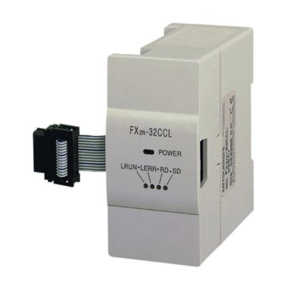
FX2N-32CCL
Mitsubishi Electric FX2N-32CCL Manuals
Manuals and User Guides for Mitsubishi Electric FX2N-32CCL. We have
4
Mitsubishi Electric FX2N-32CCL manuals available for free PDF download: Training Manual, Hardware Manual, Installation Manual
Mitsubishi Electric FX2N-32CCL Training Manual (284 pages)
Programmable Logic Controllers
Brand:
Mitsubishi Electric
| Category:
Controller
| Size: 15.38 MB
Table of Contents
Table of Contents
11
Course Overview and Requirements
17
Modular PLC Training Hardware
17
The Hardware
19
General Introduction to Plcs
19
History & Development
19
The Initial Specification for the PLC
19
Comparison of PLC and Relay Systems
19
Programming
20
Human Machine Interfaces
20
What Is a PLC
21
How Plcs Process Programs
22
The MELSEC FX Family
24
Selecting the Right Controller
25
Controller Design
27
Input and Output Circuits
27
Layout of the MELSEC FX1S Base Units
27
Layout of the MELSEC FX1N Base Units
28
Layout of the MELSEC FX2N Base Units
28
Layout of the MELSEC FX2NC Base Units
29
Layout of the MELSEC FX3G Base Units
29
Layout of the MELSEC FX3U Base Units
30
Layout of the MELSEC FX3UC Base Units
30
Wiring
31
Power Supply
31
Wiring of Inputs
32
Wiring of Outputs
33
Extending the Range of Digital Inputs/Outputs
35
Extension Boards
35
Compact Extension Units
35
Modular Extension Blocks
36
Extending for Special Functions
37
Analog Modules
38
High-Speed Counter Modules and Adapters
41
Positioning Modules
42
Network Modules for ETHERNET
43
Network Modules for Profibus/Dp
44
Network Modules for CC-Link
46
Network Module for Devicenet
47
Network Module for Canopen
47
Network Module for AS-Interface
48
Interface Modules and Adapters
49
Communication Adapters
50
Setpoint Adapter Boards
51
System Configuration
52
Connection of Special Adapters
54
Basic Rules for System Configuration
56
Quick Reference Matrixes
57
I/O Assignment
59
Concept of Assigning
59
Special Function Module Address
60
Programming
61
Concepts of the IEC61131-3 Standard
61
Software Structure and Definition of Terms
62
Definition of Terms in IEC61131-3
62
System Variables
69
System Labels
70
Programming Languages
71
Text Editors
71
Graphic Editors
72
Data Types
75
Simple Types
75
Complex Data Types
75
MELSEC Timers and Counters
80
Building a Project
81
Starting GX IEC Developer
82
Application Program
84
Example: Carousel Indexer
84
Creating a New Project
86
Creating a New "POU
88
Assigning the Global Variables
89
Programming the POU Body
94
Creating a New Task
109
Program Documentation
113
Checking and Building the Project Code
114
Illustration: Guided Ladder Entry Mode
116
Project Download Procedures
117
Connection with Peripheral Devices
117
Communications Port Setup
117
Downloading the Project
121
Monitoring the Project
123
Split / Multi Window Monitoring
124
Adjusting Monitor Visibility
126
Cross Reference List
127
PLC Diagnostics
130
Project Documentation
131
Program Example
135
An Alarm System
135
Method
136
Checking the Example Program "Alarm_System
138
Functions and Function Blocks
139
Functions
139
Example: Creating a Function
139
Processing Real (Floating Point) Numbers
148
Creating a Function Block
152
Execution Options of Function Blocks
159
Macrocode Execution
159
Enable / Enableoutput (EN/ENO)
160
Advanced Monitoring Functions
161
Entry Data Monitoring
161
Customising the EDM
162
Monitor Limitations
164
Toggling Boolean Variables
165
Monitoring Headers
166
Monitor Mode Essentials
167
Monitoring Mitsubishi "Transfer Form" Objects
169
Modifying Variable Values from the POU Body
170
Monitoring "Instances" of Function Blocks
171
Device Edit
173
Online Mode
177
Online Change Mode
177
Online Program Change
179
Data Unit Types (DUT)
181
Example Use of a DUT
182
Automatic Filling, Variables
185
Assigning DUT Variables to Function Blocks
188
Arrays
191
Overview
191
Array Example: Single Dimension Array
193
Working with Libraries
199
User Defined Libraries
199
Example - Creating a New Library
199
Opening the Library
201
Moving a POU "Function Block" to an Open Library
202
Special Note about Libraries
205
Importing Libraries into Projects
206
Import of an User Library
206
Importing a Mitsubishi Library Function Block
209
Library Function Block Help
212
Security
213
Password
213
Setting the Password
213
Changing the Security Level
214
Modifying POU Password Access
215
Sequential Function Chart - SFC
217
What Is SFC
217
SFC Elements
218
SFC Transitions
218
Initial Step
218
Termination Step
218
SFC Configuration Examples
220
SFC Actions
221
Complex Transitions
223
IEC Instruction List
225
Some Useful Tips
225
Mixing IEC IL and Melsec IL in Pous
226
IEC Structured Text
227
Structured Text Operators
227
Structured Text Program Example
228
PROFIBUS/DP Communication
231
Configuring the PROFIBUS/DP Network
231
Ethernet Communications
239
Configuring the PC on the Ethernet
240
Configuring the FX 3U -ENET by FX Configurator-EN
242
Configuring GX IEC Developer to Access the PLC on Ethernet
245
Setting up a HMI of the GOT1000 Series (GT12, GT15 or GT16)
249
Setting up a HMI of the E1000 Series
252
Communication Via MX Component
256
Special Relays
261
PLC Status Diagnostic Information (M8000 to M8009
262
Clock Devices and Real Time Clock (M8011 to M8019
262
PLC Operation Mode (M8030 to M8039
263
Error Detection (M8060 to M8069
264
Extension Boards (Dedicated to FX and FX
264
Analog Special Adapter and Adapter Boards for FX 3G
265
Special Registers
266
PLC Status Diagnostic Information (D8000 to D8009
266
Scan Information and Real Time Clock (D8010 to D8019
267
PLC Operation Mode (D8030 to D8039
267
Error Codes (D8060 to D8069
268
Extension Boards
268
Analog Special Adapter and Adapter Boards for FX
269
Error Code List
270
Error Codes 6101 to 6409
270
Error Codes 6501 to 6510
271
Error Codes 6610 to 6632
272
Error Codes 6701 to 6710
273
Number of Occupied Input/Output Points and Current Consumption
274
Interface Adapter Boards and Communication Adapter Boards
274
Special Adapters
275
Extension Blocks
275
Special Function Modules
276
PLC Components Glossary
277
Advertisement
Mitsubishi Electric FX2N-32CCL Hardware Manual (154 pages)
Brand:
Mitsubishi Electric
| Category:
Controller
| Size: 4.1 MB
Table of Contents
Table of Contents
16
Eng
21
Introduction
21
Unit Accessories
29
World Specification
29
Accessoires D'un Appareil
29
Version Internationale
29
Model Name
30
Designation des Types D'appareils
30
Serial Number
31
Numéro de Serie
31
Configuration
32
Configuration du Système
32
Rules
35
Règles de Base Relatives À la Construction du Système
35
Terminal Layouts
39
Occupation des Bornes
39
Relay Out, 24V DC Input Mpu's - Main Processing Unit (Base Units)
40
Appareils de Base Avec Sorties de Relais Et Entrées 24V CC
40
Transistor Output, Mpu's - (Base Units)
41
Appareils de Base Avec Sorties de Transistor
41
Powered Extension Units
42
Extension Blocks
42
Appareils D'extension Alimentés en Tension
42
Modules D'extension
42
FX0N Extension Blocks
43
AC 110V Input, Mpus - (Base Units)
44
Appareils de Base Avec Entrées 110V CA
44
Installation
45
Product Outline
46
Description de L'appareil
46
RUN/STOP Control
48
Commande Run/Stop
49
General Specifications
50
Caractéristiques Générales
50
PLC Mounting Arrangements
52
Montage de L'api
52
DIN Rail Mounting
55
Montage de L'appareil Sur Rail DIN
55
Direct Mounting
56
Montage Direct
56
General Notes
57
Instructions Générales
57
Extension Board Installation
58
Installation de la Carte D'extension
58
Extension Units/Blocks Installation
60
Installation D'extensions
60
Wiring Techniques
61
Wiring Cautions
61
Raccordement Électrique
61
Instructions Relatives Au Cablage
62
Termination at Screw Terminals
64
Removal and Installation of Quick-Release Terminal Block
67
Enlèvement Et Installation du Bloc de Bornes À Déclenchement Instantané
67
Power Supply
69
Alimentation en Tension
69
Earthing/Grounding
75
Mise À la Terre
75
Service Power Supply
76
Alimentation en Tension de Service
76
Inputs
79
DC Input Specifications
79
Caractéristiques Techniques des Entrées Pour 24 V CC
79
Typical Wiring
80
Exemple de Câblage
80
Input Circuit Connection
81
Circuit D'entrée
81
Diodes and Inputs Connected in Series
82
Diodes Et Entrées Montées en Série
82
Resistors and Inputs Connected in Parallel
83
Résistance Et Entrée Montées en Parallèle
83
AC 110V Input, Mpus
84
Appareils de Base Avec Entrées 110V CA
84
AC Input Specifications
85
Caractéristiques Techniques des Entrées Pour 110 V CA
85
Typical Wiring
86
Exemple de Câblage
86
Programming Caution
87
Instructions Relatives À la Programmation
87
Outputs
89
Relay Output Specification
89
Caractéristiques Techniques des Sorties des Relais
89
Product Life of Relay Contacts
91
Longévité des Produits des Contacts À Relais
92
Relay Output Example
96
Output Circuit Configuration
97
Configuration du Circuit de Sortie
97
Triac (SSR) Output Specifications
100
Caractéristiques Techniques des Sorties Triac (SSR)
100
In-Rush Currents
102
Impulsions de Courant
102
Triac Output Example
103
Caractéristiques Techniques des Sorties Triac
103
Output Circuit Configuration
104
Configuration du Circuit de Sortie
104
Transistor Output Specification
106
Caractéristiques Techniques des Sorties des Transistors
106
Response Times
108
Temps de Réponse
108
Transistor Output Example
109
Exemple D'un Câblage de Sortie de Transistor
109
Applying Safe Loads
110
Prescriptions de Sécurité Pour la Mise en Circuit de Charges
110
Diagnostics
111
Preliminary Checks
111
Vérifications À Effectuer Avant la Mise en Service
111
Basic Diagnostics
112
Power ON, PLC off
112
Diagnostic D'erreurs Général
112
Tension MARCHE, API ARRET
112
Batt.V Led on
114
LED BATT.V S'allume
114
PROG.E LED Flashes
116
Led Prog.e
116
Cpu.e Led on
117
La LED CPU.E Est Allumée
117
Common Errors
120
Autres Causes D'erreurs
120
Replacing the Battery
121
Remplacement de la Batterie
121
Maintenance
123
Entretien
123
Error Flags on Indicates Error
124
Indicateurs D'erreurs "MARCHE" Désigne Une Erreur
124
Error Registers
126
Error Codes
128
Codes D'erreurs
128
Instruction List
129
Vue D'ensemble des Instructions Relatives Aux Applications
129
Appendix A: Associated Manuals
133
Appendix A:autres Manuels
133
Appendix B: Discontinued Models
137
Appendix B:modèles Abandonnés
137
Appendix C: Index
149
Mitsubishi Electric FX2N-32CCL Hardware Manual (140 pages)
PROGRAMMABLE CONTROLLERS
Brand:
Mitsubishi Electric
| Category:
Controller
| Size: 2.31 MB
Table of Contents
Table of Contents
7
Unit Accessories
21
World Spec
21
Model Name
22
Serial Numbers
23
Configuration
24
Current Consumption and Input/Output Points
28
Rules
32
System Configuration Example
35
Quick Judgment
38
Terminal Layouts
41
Main Units
43
FX 2NC Extension Blocks
45
FX 2N and FX 0N Extension Blocks
46
Installation Notes
47
FX 2NC RUN/STOP Control
52
General Specifications
54
PC Mounting Arrangements
55
Connection of Extension Blocks to Main Unit
57
DIN Rail Mounting
57
Direct Mounting
58
Extension Cable Installation
62
General Notes
63
Memory Board Installation
64
Wiring Techniques
65
Termination of Connector Style I/O
66
Termination of Screw Terminals
67
Termination of Connector Style I/O Cables
68
Power Supply
69
Power Supply Cautions
75
Earthing / Grounding
76
Inputs
77
DC Input Specifications
79
Typical Wiring
80
Input Circuit Connection
82
Diodes and Inputs Connected in Series
84
Resistors and Inputs Connected in Parallel
85
AC110V Input Extension Block
86
Input Circuit Connection
86
Programming Caution
87
Outputs
89
Transistor Output Specification
91
Response Times
92
Output Circuit Configuration
93
Transistor Output Example
94
Relay Output Specification
96
Product Life of Relay Contacts
97
Output Circuit Configuration
99
Relay Output Example
101
Triac (SSR) Output Specifications
103
In-Rush Currents
104
Output Circuit Configuration
105
Triac Output Example
107
Applying Safe Loads
107
Diagnostics
109
Preliminary Checks
111
Basic Diagnostics
112
Batt Led on
112
ERROR LED Flashes (PROGRAM ERROR)
112
Error Led on (Cpu Error)
113
Common Errors
114
Writing of Program and Program Check [Power on and PLC Stopped]
115
Replacing the Battery
116
Maintenance
118
Error Flags on Indicates Error
119
Error Registers
121
Error Codes
123
Instruction List
124
Discontinued Model
129
Appendix
133
Precautions for Battery Transportation
135
Regulated FX 2NC Series Products
135
Transport Guidelines
135
Handling of Batteries and Devices with Built-In Batteries in EU Member States
136
Disposal Precautions
136
Exportation Precautions
137
Advertisement
Mitsubishi Electric FX2N-32CCL Installation Manual (3 pages)
MELSEC-F/FX2N Series
Brand:
Mitsubishi Electric
| Category:
Controller
| Size: 0.63 MB
Advertisement
Related Products
Mitsubishi Electric FX2N-32
Mitsubishi Electric FX2N-32E series
Mitsubishi Electric FX2N-32ASI-M
Mitsubishi Electric MELSEC FX2N-32DP-IF
Mitsubishi Electric MELSEC FX2N-32ASI-M 3
Mitsubishi Electric FX2N-1PG
Mitsubishi Electric MELSEC FX2N-8ER-ES/UL
Mitsubishi Electric MELSEC FX2NC-485ADP 2
Mitsubishi Electric FX2N-CNV-IF
Mitsubishi Electric MELSEC FX2N-232IMELSEC F
Mitsubishi Electric Categories
Air Conditioner
Controller
Projector
Inverter
Heat Pump
More Mitsubishi Electric Manuals
Login
Sign In
OR
Sign in with Facebook
Sign in with Google
Upload manual
Upload from disk
Upload from URL