Sign In
Upload
Manuals
Brands
Fujitsu Manuals
Storage
ETERNUS DX600 S4
Fujitsu ETERNUS DX600 S4 Storage System Manuals
Manuals and User Guides for Fujitsu ETERNUS DX600 S4 Storage System. We have
5
Fujitsu ETERNUS DX600 S4 Storage System manuals available for free PDF download: Operation Manual, Configuration Manual, Safety Precautions
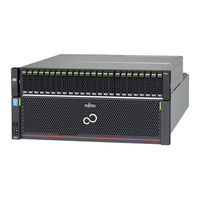
Fujitsu ETERNUS DX600 S4 Operation Manual (79 pages)
Hybrid Storage Systems
Brand:
Fujitsu
| Category:
Storage
| Size: 2.8 MB
Table of Contents
Table of Contents
2
About this Manual
8
Document Conventions
8
Intended Audience
8
1 Component Names and LED Names
10
Controller Enclosures
10
Front
10
Figure 1 Front View of a Controller Enclosure (with a Front Cover)
10
Figure 2 Front View of a Controller Enclosure (Without a Front Cover)
11
Rear
12
Figure 3 Rear View of a Controller Enclosure (ETERNUS DX500 S4/DX500 S3)
12
Figure 4 Rear View of a Controller Enclosure (ETERNUS DX600 S4/DX600 S3)
12
Components (Front)
13
Figure 5 Operation Panel (Controller Enclosure)
13
Figure 6 PFM
14
Table 1 Status and Meanings of each LED (Operation Panel (Controller Enclosure))
14
Table 2 Status and Meanings of each LED (PFM)
14
Figure 7 Battery
15
Table 3 Status and Meanings of each LED (Battery)
15
ETERNUS DX500 S4/DX600 S4 Components (Rear)
16
Figure 8 Controller (ETERNUS DX500 S4)
16
Figure 9 Controller (ETERNUS DX600 S4)
17
Figure 10 Controller Leds
18
Table 4 Status and Meanings of each LED (Controller)
18
Figure 11 Host Interface for FC Cable Connections (4Port)
19
Figure 12 Host Interface for LAN Cable Connections (4Port)
19
Figure 13 Host Interface for FC Cable Connections (2Port, Equipped with SFP+ Modules in All Ports)
20
Figure 14 Host Interface for Copper Twinax Cable Connections (2Port)
20
Figure 15 Host Interface for LAN Cable Connections (2Port)
21
Table 5 Status and Meanings of each LED (Host Interface)
21
Figure 16 Power Supply Unit (Controller Enclosure)
22
Table 6 Status and Meanings of each LED (Power Supply Unit)
22
ETERNUS DX500 S3/DX600 S3 Components (Rear)
23
Figure 17 Controller (ETERNUS DX500 S3)
23
Figure 18 Controller (ETERNUS DX600 S3)
24
Figure 19 Controller Leds
25
Table 7 Status and Meanings of each LED (Controller)
25
Figure 20 Host Interface (4Port)
26
Figure 21 Host Interface (2Port)
26
Figure 22 Power Supply Unit (Controller Enclosure)
27
Table 8 Status and Meanings of each LED (Host Interface)
27
Table 9 Status and Meanings of each LED (Power Supply Unit)
27
2.5"/3.5" Type Drive Enclosures
28
Front
28
Figure 23 Front View of a 2.5" Type Drive Enclosure
28
Figure 24 Front View of a 3.5" Type Drive Enclosure
28
Rear
29
Components (Front)
29
Figure 25 Rear Views of a 2.5"/3.5" Type Drive Enclosure
29
Figure 26 Operation Panel (2.5"/3.5" Type Drive Enclosure)
29
Figure 27 2.5" Drives
30
Figure 28 Drive Slot Numbers (2.5" Type Drive Enclosure)
30
Table 10 Status and Meanings of each LED (Operation Panel (2.5"/3.5" Type Drive Enclosure))
30
Figure 29 3.5" Drives
31
Figure 30 Drive Slot Numbers (3.5" Type Drive Enclosure)
31
Table 11 Status and Meanings of each LED (Drive (Drive Enclosure) (2.5"/3.5" Type))
31
Components (Rear)
32
Figure 31 I/O Module (2.5"/3.5" Type Drive Enclosure)
32
Table 12 Status and Meanings of each LED (I/O Module (2.5"/3.5" Type Drive Enclosure))
32
Figure 32 Power Supply Unit (2.5"/3.5" Type Drive Enclosure)
33
Table 13 Status and Meanings of each LED (Power Supply Unit (2.5"/3.5" Type Drive Enclosure))
33
High-Density Drive Enclosure
34
Front
34
Rear
34
Figure 33 Front View of a High-Density Drive Enclosure
34
Figure 34 Rear View of a High-Density Drive Enclosure
34
Components (Front)
35
Figure 35 Operation Panel (High-Density Drive Enclosure)
35
Table 14 Status and Meanings of each LED (Operation Panel (High-Density Drive Enclosure))
35
Figure 36 Disk Activity Panel (DAP)
36
Table 15 Status and Meanings of each LED (Disk Activity Panel (DAP))
36
Components (Internal)
37
Figure 37 Drives for High-Density Drive Enclosures
37
Figure 38 Drive Slot Numbers for High-Density Drive Enclosures
37
Components (Rear)
38
Figure 39 I/O Module (High-Density Drive Enclosure)
38
Table 16 Status and Meanings of each LED (I/O Module (High-Density Drive Enclosure))
38
Figure 40 Fan Expander Module
39
Table 17 Status and Meanings of each LED (Fan Expander Module)
39
Figure 41 Power Supply Unit (High-Density Drive Enclosure)
40
Table 18 Status and Meanings of each LED (Power Supply Unit (High-Density Drive Enclosure))
40
19-Inch Racks
41
Front
41
Figure 42 Front View of a 19-Inch Rack
41
Rear
42
Figure 43 Rear View of a 19-Inch Rack
42
Power Distribution Units (for Regions Other than the EMEIA, Central American, and Caribbean Re- Gions)
43
Power Distribution Units (1U)
43
Figure 44 Power Distribution Unit (AC200-240V, 1U, 4 Outlets)
43
Figure 45 Power Distribution Unit (AC200-240V, 1U, 4 Outlets)
43
Power Distribution Units (2U)
44
Figure 46 Power Distribution Unit (AC200-240V, 2U, 12 Outlets)
44
Figure 47 Power Distribution Unit (AC200-240V, 2U, 16 Outlets)
45
Figure 48 Power Distribution Unit (AC200-240V, 2U, 16 Outlets)
45
2 Basic Operation
46
How to Open/Close the Rack Doors
46
How to Open/Close the Front Door
46
How to Open/Close the Rear Door
47
Powering on and off
49
Switching on and off the Main Line Switch on the Power Distribution Unit (for Regions Other than the EMEIA, Central American, and Caribbean Regions)
49
Figure 49 on Position (Marked "|") of the Main Line Switches on a 1U Power Distribution Unit
49
Figure 50 on Position of the Main Line Switches on a 1U Power Distribution Unit
49
Figure 51 on Position (Marked "|") of the Main Line Switches on a 2U Power Distribution Unit
50
Figure 52 on Position of the Main Line Switches on a 2U Power Distribution Unit
50
Figure 53 off Position (Marked "¡") of the Main Line Switches on a 1U Power Distribution Unit
51
Figure 54 off Position of the Main Line Switches on a 1U Power Distribution Unit
51
Figure 55 off Position (Marked "¡") of the Main Line Switches on a 2U Power Distribution Unit
52
Figure 56 off Position of the Main Line Switches on a 2U Power Distribution Unit
52
Switching on and off the PSU Switch on the Power Supply Unit
53
Figure 57 on Position (Marked "|") of the PSU Switch on a Power Supply Unit
53
Powering on
54
Figure 58 off Position (Marked "¡") of the PSU Switch of a Power Supply Unit
54
Powering off
56
Using the Setting Change Switches
58
3 Storage System Monitoring
60
Checking LED Status
60
Displaying Status Via ETERNUS Web GUI
60
Figure 59 ETERNUS Web GUI Screen
60
Table 19 General Status of ETERNUS Web GUI
60
Displaying Status Via ETERNUS CLI
61
Event Notification
61
Table 20 General Status of ETERNUS CLI
61
Figure 60 Event Notification
62
Audit Log
63
Figure 61 Audit Log
63
4 Process Time (Estimated)
64
Volume Formatting Time
64
Table 21 Volume Formatting Time
64
Rebuild/Copyback Process Time
65
Table 22 Rebuild Process Time
65
Table 23 Copyback Process Time
65
5 Expansion Functions
67
6 Maintenance
68
Periodic Backup
68
Maintenance Service
68
Maintenance Support Period
68
Replacing Batteries
69
Related Service
69
7 Troubleshooting
70
Check List
70
Required Information for Inquiries
77
Advertisement
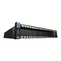
Fujitsu ETERNUS DX600 S4 Configuration Manual (78 pages)
Hybrid Storage Systems / Disk Storage Systems / All-Flash Arrays, ETERNUS DX S4 Series, ETERNUS DX S3 Series. ETERNUS AF Series
Brand:
Fujitsu
| Category:
Storage
| Size: 1.6 MB
Table of Contents
Using this Manual
3
Compliance with Standards
4
About this Manual
6
Symbols Used in this Manual
8
Safety Precautions
9
Table of Contents
17
Chapter 1 Overview
21
External View
21
Figure 1.1 External View of a Power Synchronized Unit
21
Figure 1.2 External View of an AC Sensor Unit
21
Features
22
Specifications
23
Table 1.1 Specifications
23
Components
24
Power Synchronized Unit
24
Figure 1.3 Components (Power Synchronized Unit)
24
Table 1.2 Status and Meanings of each LED (for Power Synchronized Units)
25
AC Sensor Unit (Optional)
26
Figure 1.4 Components (AC Sensor Unit)
26
Table 1.3 Status and Meanings of each LED (for AC Sensor Units)
26
System Configuration
27
Figure 1.5 System Configuration Example (Power Synchronization with Two Server UPS Units)
27
Figure 1.6 System Configuration Example (Power Synchronization with Three or more Server UPS Units)
28
Power Management for Power Synchronization
29
Figure 1.7 Power on Using a Power Synchronized Unit
29
Figure 1.8 Operation Timing Chart When Using a Power Synchronized Unit (Powering On)
30
Figure 1.9 Power off Using a Power Synchronized Unit
31
Figure 1.10 Operation Timing Chart When Using a Power Synchronized Unit (Powering Off)
32
Chapter 2 Installation
33
Package Contents Check
33
Table 2.1 List of Package Contents (Power Synchronized Unit)
33
Table 2.2 List of Package Contents (AC Sensor Unit)
33
Preparation
34
Installation Area
34
Checking Power Sockets and Server UPS Unit Outlets
34
Preparing Power Cords
34
Installing in a Rack
35
Installing a Power Synchronized Unit
36
Installing an AC Sensor Unit
39
Chapter 3 Powering on and off
43
Chapter 4 Connection and Settings
44
Setting the ETERNUS DX/AF
45
Figure 4.1 ETERNUS DX60 S4/DX100 S4/DX200 S4, ETERNUS DX500 S4/DX600 S4
45
Figure 4.2 ETERNUS DX8700 S3/DX8900 S3 Setup (Setup Power Management Screen)
47
Figure 4.3 ETERNUS DX80 S2/DX90 S2 Setup (Setup Power Management Screen)
48
Figure 4.4 ETERNUS DX60 S2 Setup (Setup Power Management Screen)
49
Turning on the Power Synchronized Unit
50
Connecting Cascade Cables
53
Figure 4.5 Cascade Cable Connection
53
Connecting to the Server UPS Unit
56
Figure 4.6 Connection for the Server UPS Units and the AC Sensor Units
56
Connecting the Server UPS Unit to the Power Synchronized Unit
57
Connecting the AC Sensor Unit
58
Connecting to the ETERNUS DX/AF
61
Checking after Connection
64
Chapter 5 Adding a Connecting Device
65
Connection Procedure When Adding a Server
65
Connection Procedure When Adding an ETERNUS DX/AF
67
Chapter 6 Operation and Maintenance
71
Checking the Power Synchronized Unit Status
71
Device Replacement after Operation Startup
71
Replacing a Server
71
Replacing a Power Synchronized Unit
72
Replacing an AC Sensor Unit
72
Troubleshooting
73
Check List
73
Trouble Record
76
Figure 6.1 Trouble Record
76
Fujitsu ETERNUS DX600 S4 Configuration Manual (75 pages)
All-Flash Arrays, Hybrid Storage Systems, Disk Storage Systems, Power Synchronized Unit
Brand:
Fujitsu
| Category:
Storage
| Size: 4 MB
Table of Contents
Table of Contents
2
Overview
20
External View
20
Figure 1 External View of a Power Synchronized Unit
20
Figure 2 External View of an AC Sensor Unit
20
Features
21
Specifications
22
Components
23
Power Synchronized Unit
23
Figure 3 Components (Power Synchronized Unit)
23
AC Sensor Unit (Optional)
25
Figure 4 Components (AC Sensor Unit)
25
System Configuration
26
Figure 5 System Configuration Example (Power Synchronization with Two Server UPS Units)
26
Figure 6 System Configuration Example (Power Synchronization with Three or more Server UPS Units)
27
Power Management for Power Synchronization
28
Figure 7 Power on Using a Power Synchronized Unit
28
Figure 8 Operation Timing Chart When Using a Power Synchronized Unit (Powering On)
28
Figure 9 Power off Using a Power Synchronized Unit
30
Figure 10 Operation Timing Chart When Using a Power Synchronized Unit (Powering Off)
31
Installation
32
Package Contents Check
32
Preparation
32
Installation Area
32
Checking Power Sockets and Server UPS Unit Outlets
33
Preparing Power Cords
33
Installing in a Rack
34
Installing a Power Synchronized Unit
35
Installing an AC Sensor Unit
38
Powering on and off
42
Connection and Settings
43
Setting the ETERNUS DX/AF
44
Figure 11 ETERNUS AF Series, ETERNUS DX S5/S4/S3 Series
44
Figure 12 ETERNUS DX900 S5, ETERNUS DX8900 S4, and ETERNUS DX8700 S3/DX8900 S3 Setup
45
Figure 13 ETERNUS DX80 S2/DX90 S2 Setup (Setup Power Management Screen)
46
Figure 14 ETERNUS DX60 S2 Setup (Setup Power Management Screen)
47
Turning on the Power Synchronized Unit
48
Connecting Cascade Cables
51
Figure 15 Cascade Cable Connection
51
Connecting to the Server UPS Unit
53
Figure 16 Connection for the Server UPS Units and the AC Sensor Units
53
Connecting the Server UPS Unit to the Power Synchronized Unit
54
Connecting the AC Sensor Unit
55
Connecting to the ETERNUS DX/AF
57
Checking after Connection
61
Adding a Connecting Device
62
Connection Procedure When Adding a Server
62
Connection Procedure When Adding an ETERNUS DX/AF
64
Operation and Maintenance
68
Checking the Power Synchronized Unit Status
68
Device Replacement after Operation Startup
68
Replacing a Server
68
Replacing a Power Synchronized Unit
69
Replacing an AC Sensor Unit
70
Troubleshooting
71
Check List
71
Trouble Record
73
Figure 17 Trouble Record
73
Advertisement
Fujitsu ETERNUS DX600 S4 Configuration Manual (18 pages)
Non-Stop Storage ETERNUS AF series and ETERNUS DX S4/S3 series
Brand:
Fujitsu
| Category:
Storage
| Size: 1.1 MB
Table of Contents
Table of Contents
2
Preface
3
1 Overview of Non-Stop Storage Solution
4
Features of Non-Stop Storage Solution
4
Suitable Systems for Non-Stop Storage
4
Protecting Investment and Optimizing Investment Cost
5
FUJITSU Storage ETERNUS SF Software for Non-Stop Storage Operation
5
2 System Configuration
7
Example of a Non-Stop Storage Configuration
8
Management Server
9
Example of a Non-Stop Storage Configuration (with Redundant Management Servers)
12
Hardware Layout
13
Workflow for System Configuration
15
3 Conclusion
18
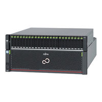
Fujitsu ETERNUS DX600 S4 Safety Precautions (12 pages)
Hybrid Storage Systems, All-Flash Arrays, Power Synchronized Unit
Brand:
Fujitsu
| Category:
Storage
| Size: 0.58 MB
Table of Contents
Instructions for Installation
2
Handling Instructions
3
Handling Cables
5
Handling Batteries
5
Advertisement
Related Products
Fujitsu ETERNUS DX60
Fujitsu ETERNUS DX60 S2
Fujitsu Eternus DX600 S3
Fujitsu ETERNUS DX60 S3
Fujitsu ETERNUS DX60 S4
Fujitsu ETERNUS DX60 S5
Fujitsu ETERNUS DX600 S5
Fujitsu ETERNUS DX60 DX80 S2
Fujitsu ETERNUS DX60 DX90 S2
Fujitsu ETERNUS DX600 S6
Fujitsu Categories
Air Conditioner
Laptop
Server
Scanner
Storage
More Fujitsu Manuals
Login
Sign In
OR
Sign in with Facebook
Sign in with Google
Upload manual
Upload from disk
Upload from URL