Table of Contents
Advertisement
Quick Links
INSTALLATION INSTRUCTIONS 30" (76.2 CM)
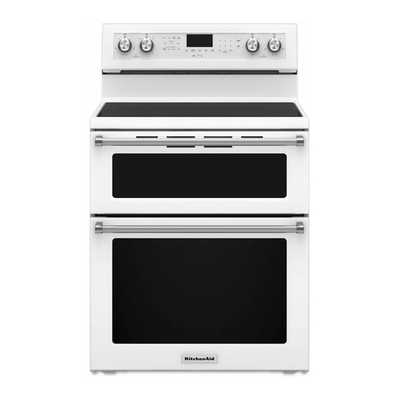
FREESTANDING ELECTRIC RANGE WITH DOUBLE OVENS
We have provided many important safety messages in this manual and on your appliance. Always read and obey all safety
messages.
This is the safety alert symbol.
This symbol alerts you to potential hazards that can kill or hurt you and others.
All safety messages will follow the safety alert symbol and either the word "DANGER" or "WARNING."
These words mean:
DANGER
WARNING
All safety messages will tell you what the potential hazard is, tell you how to reduce the chance of injury, and tell you what can
happen if the instructions are not followed.
IMPORTANT:
Save for local electrical inspector's use.
W10694065A
Table of Contents
RANGE SAFETY .............................................................................1
INSTALLATION REQUIREMENTS ................................................2
Tools and Parts ............................................................................2
Location Requirements ................................................................2
Electrical Requirements ...............................................................4
INSTALLATION INSTRUCTIONS ..................................................5
Unpack Range..............................................................................5
Adjust Leveling Legs ....................................................................5
Install Anti-Tip Bracket .................................................................6
Electrical Connection ...................................................................7
Verify Anti-Tip Bracket Is Installed and Engaged ......................12
Level Range................................................................................12
Complete Installation..................................................................12
Moving the Range ......................................................................13
RANGE SAFETY
Your safety and the safety of others are very important.
You can be killed or seriously injured if you don't immediately
follow instructions.
You can be killed or seriously injured if you don't follow
instructions.
Advertisement
Table of Contents

Summary of Contents for KitchenAid KFED500EWH
-
Page 1: Table Of Contents
INSTALLATION INSTRUCTIONS 30" (76.2 CM) FREESTANDING ELECTRIC RANGE WITH DOUBLE OVENS Table of Contents RANGE SAFETY ................1 INSTALLATION REQUIREMENTS ..........2 Tools and Parts ................2 Location Requirements ..............2 Electrical Requirements ...............4 INSTALLATION INSTRUCTIONS ..........5 Unpack Range................5 Adjust Leveling Legs ..............5 Install Anti-Tip Bracket ..............6 Electrical Connection ..............7 Verify Anti-Tip Bracket Is Installed and Engaged ......12 Level Range................12... -
Page 2: Installation Requirements
WARNING Tip Over Hazard A child or adult can tip the range and be killed. Install anti-tip bracket to floor or wall per installation instructions. Slide range back so rear range foot is engaged in the slot of the anti-tip bracket. Re-engage anti-tip bracket if range is moved. - Page 3 Product Dimensions Cabinet Dimensions Cabinet opening dimensions shown are for 25" (63.5 cm) countertop depth, 24" (61.0 cm) base cabinet depth and 36" (91.4 cm) countertop height. IMPORTANT: If installing a range hood or microwave hood combination above the range, follow the range hood or microwave hood combination installation instructions for dimensional clearances above the cooktop surface.
-
Page 4: Electrical Requirements
Electrical Requirements If codes permit and a separate ground wire is used, it is If connecting to a 4-wire system: recommended that a qualified electrical installer determine that This range is manufactured with the ground connected to the the ground path and wire gauge are in accordance with local neutral by a link. -
Page 5: Installation Instructions
INSTALLATION INSTRUCTIONS Unpack Range Adjust Leveling Legs 1. If range height adjustment is necessary, use a wrench or pliers to loosen the 4 leveling legs. WARNING This may be done with the range on its back or with the range supported on 2 legs after the range has been placed back to Excessive Weight Hazard a standing position. -
Page 6: Install Anti-Tip Bracket
Install Anti-Tip Bracket 4. Drill two ¹⁄₈" (3.0 mm) holes that correspond to the bracket WARNING holes of the determined mounting method. See the following illustrations. Floor Mounting Wall Mounting Tip Over Hazard A child or adult can tip the range and be killed. Install anti-tip bracket to floor or wall per installation instructions. -
Page 7: Electrical Connection
Electrical Connection Power Supply Cord Direct Wire WARNING WARNING Electrical Shock Hazard Electrical Shock Hazard Disconnect power before servicing. Disconnect power before servicing. Use a new 40 amp power supply cord. Use 8 gauge copper or 6 gauge aluminum wire. Plug into a grounded outlet. - Page 8 Style 2: Direct wire strain relief ■ Tighten strain relief screw against the flexible conduit. ■ Use Phillips screwdriver to remove screws and slide cord/conduit plate down and out. 5. Replace back panel and screws on rear of range. 6. Complete installation following instructions for your type of electrical connection: 4-wire (recommended) 3-wire (if 4-wire is not available)
- Page 9 5. Use ³⁄₈" nut driver to connect the neutral (white) wire to the 4-wire Connection: Power Supply Cord center terminal block post with one of the 10-32 hex nuts. Use this method for: ■ New branch-circuit installations (1996 NEC) ■ Mobile homes ■...
- Page 10 2. Use ³⁄₈" nut driver to connect the neutral (white) wire to the 4-wire Connection: Direct Wire center terminal block post with one of the 10-32 hex nuts. Use this method for: ■ New branch-circuit installations (1996 NEC) ■ Mobile homes ■...
- Page 11 4. Attach terminal lugs to line 1 (black), neutral (white), and line 2 3-wire Connection: Direct Wire (red) wires. Loosen (do not remove) the setscrew on the front of the terminal lug and insert exposed wire end through bottom of terminal lugs. Securely tighten the setscrew to the Use this method only if local codes permit connecting ground torque shown in the Bare Wire Torque Specifications chart.
-
Page 12: Verify Anti-Tip Bracket Is Installed And Engaged
3. Use ³⁄₈" nut driver to connect the bare (green) ground wire to 4. Slide the range forward, and verify that the anti-tip bracket is the center terminal block post with one of the 10-32 hex nuts. securely attached to the floor or wall. 5. -
Page 13: Moving The Range
Moving the Range For direct-wired ranges: WARNING WARNING Tip Over Hazard Electrical Shock Hazard A child or adult can tip the range and be killed. Disconnect power before servicing. Install anti-tip bracket to floor or wall per installation Replace all parts and panels before operating. instructions. - Page 14 Notes...
- Page 15 Notes...
- Page 16 9/14 W10694065A ® /™ ©2014 All rights reserved. Printed in U.S.A.


